Many model elements that you create from toolbox elements have life-cycle tagged values; namely Actual Begin Date, Actual Start Date, Planned Begin Date, and Planned End Date. These dates are used to determine the deployment status in the SQL views. Some connectors also have life-cycle tags and Roadmap Phases have Begin and End Date tags. The combinatio of these life-cycle tags provides three levels of life-cycle reporting used in the (EA)<sup>2</sup> SQL views, as explained below. The format of the date tagged value,which is also explained below, is very important.
The status field in the element's Sparx EA properties dialog is independent of these dates and the deployment status in the SQL views that is calculated from the dates. you can use the EA status field with the values provided by (EA)<sup>2</sup> to provide a color scheme to your elements acccording to their status, but please note that the Sparx EA status does not track to the life-cycle. You have to set it independently if you want to use it.
Date Format
Enterprise Architect allows you to define the format of tagged values including date formats. However, we have chosen not to use this technique and, instead, have left the format as a simple string. The reason is that, when setting future dates, you often do not know the exact date when something will happen. For example, you may be planning to commission a new technology at some point in the future, say in 2011, but your plans are not specific yet. By leaving the format open, you can simply enter 2011 rather than a phony date with month and day. If you do know the month as well, you can enter 2010-03. And, of course, if you do know the full date, you can enter 2010-03-29.You should use one of these three formats in order for the SQL reporting to work properly. Again, the formats are:
<blank>
YYYY
YYYY-MM
YYYY-MM-DD
Configuration Item Life-cycles
Configuration items are model elements like Business Apps and Servers. They have life-cycle dates to indicate their deployment status. The SQL views use the (EA)<sup>2</sup> fnDeploymentStatus user-defined function to determine the deployment status of the item. There is an (EA)<sup>2</sup> SQL view that shows over a 5 year time line what configuration items will be commissioned, continued to be used, or decommisioned during each year, based on the configuration items life-cycle tags. See FiveYearTimeLine.
Connector Life-cycles
The EA2 Provides App Capability and EA2 Provides IT Capability have life-cycles on them to indicate when the connection is active. For example, a Business App provides an App Capability to a business Activity. The life-cycle tags on the connector indicate when the Business App provides the capability to that Activity. This lets you have connections from two different Business Apps to the Activity and indicate that at any given point in time, only one is active. The same is true for EA2 Provides IT Capability connectors from IT Software to Business Apps.
The net result of this is that not only can you indicate, for example, when a particular IT Software element will be retired, but you can also show when its use for a particular Business App will be retired, thus showing the staged retirement of the IT Software element. There is another (EA)<sup>2</sup> view that shows what IT Software is used by the Business Software and along with the dates.
Roadmap Life-cycles
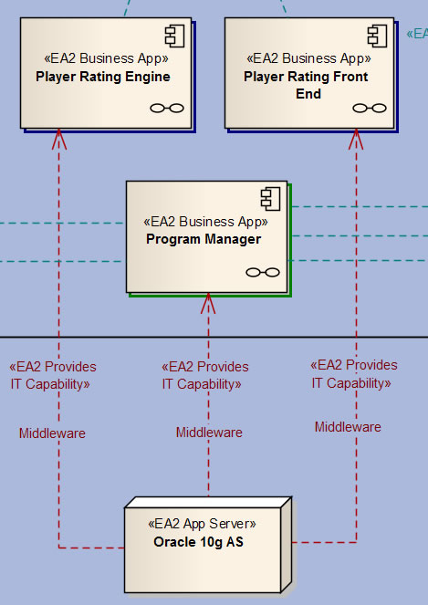
Setting all of these life-cycle dates can be tedious, especially during your planning stages. Roadmap Phases provide a broad brush approach to illustrating the different stages of your architectural development. Each Roadmap Phase is given its own Begin Date and End Date. Placing a Roadmap Phase onto a Vertical Slice diagram marks the diagram with the Roadmap's life-cycle for reporting purposes. The VerticalSliceWithCapabilities SQL view selects all of the elements on the diagram to include in its results. Furthermore, its looks at the connectors on the diagram as well. For example, an IT App may provide a capability to a Business App, but unless the connector between the two appears on the diagram, that relationship will not be included in the view results. Consider the following fragment from a Vertical Slice diagram.
We see that Oracle 10g AS is providing a Middleware capabilty to three Business Apps. Now suppose that this is a future state diagram which is showing the phased deployment of Oracle 10g AS. We can indicate when Oracle will first be deployed by setting its Planned Start Date. Now consider a phased approach to introducing Oracle into your IT environment.
Let ssy that, during phase 1, the Program Manager gets integrated with Oracle. In phase 2, the Player Rating Front End and Player Rating Engine get integrated. Both our phase 1 and phase 2 diagrams would show all of the elements. However, the phase 1 diagram would not include the connectors from Oracle to the Player Rating Front End and Player Rating Engine, whereas our phase 2 diagram would. The phase 1 report would only show Oracle working with the Program Manager, while the phase 2 report would show it working for all three. This would occur regardless of the life-cycle dates for the elements and the connectors. This makes it easy to plan the big picture and then fill in the details over time.