|
Follow the steps below to create a new Server.
Create the Server from the appropriate Server Model.
Create a Server instance by dragging the Server Model onto a diagram while holding the Control-key and selecting Include Embedded Elements (see section 2.4.5 above). Provide an appropriate name for the Server. You can use the alias to give it a more descriptive name, e.g. Name: SCMS-202, Alias: Rating Engine.
Add Tagged Values
Enter the values for the tags. As you can see in the diagram below, there are two sets of tagged values for each Server. The first set is for the Server itself. Below that is the set for the Server Model. Entering a new value in one of the Server Model's tags places the new value in the set of tags for the Server, effectively overriding the default provided by the Server.
Add Deployed Components
Add embedded elements representing the items deployed on the Server. For example, drag an Operating System onto the Server (if one was not provided by the Server Model). Drag the Business and IT Apps that are deployed on the Server. You can drag a Network Adapter from the (EA)<sup>2</sup> Infrastructure Architecture Toolbox onto the Server and give an IP address. You can add an port on an application to indicate what port it listens on and draw a CommuncationPath from the port to the Network Adapter. It also shows what services are dependent on Oracle and what DB Schemas are managed by it.
The figure below shows an example of a Server that has additional elements configured.
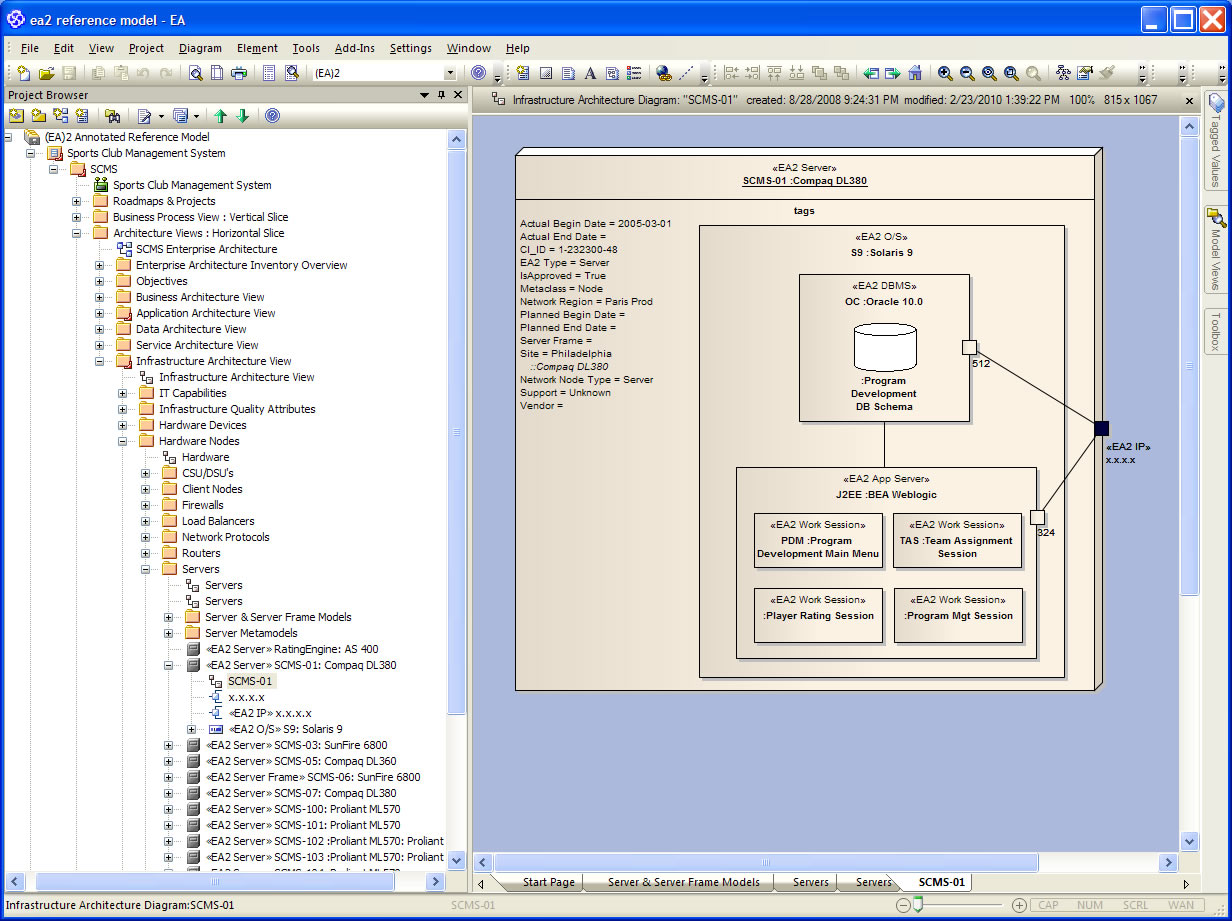
As you can see on the diagram, Solaris 9 is the operating system. It was created by dragging Solaris 9 from the Project Browser onto the Server. Next, the Oracle 11g DBMS was dragged onto the operating system and the Program Development DB Schema was dragged onto the DBMS. A EJB container was created by dragging the BEA Weblogic application server onto the operating system. Finally, the various <<Work Sessions>> were dragged onto the application server. You could map the work sessions down to their actually deployable parts (UML artifacts) and show them being deployed. However, this is generally considered too detailed for the architectural view and strategic planning.
The last steps include putting ports on the execution environments (the DBMS and App Server), for them to listen on and an IP address through which they communicate with other elements on the network. To see a network topology with Server connected together via network paths, see Sites and Network Topologies. On it you will also see the use of alternate images to make your diagrams more "Visio-like."
|